Segmentation
Image segmentation is the process of dividing an image into meaningful parts, such as objects and background. Objects are sets of adjacent pixels. Meaning the pixels touch either side-by-side or diagonally, forming a continuous shape.
Segmented objects are easier to analyze as they can be counted or measured.
Threshold
Thresholding is the simplest segmentation method available.
Threshold
Separates objects from the background by turning pixels with values inside given intensity range into objects and everything else into background.
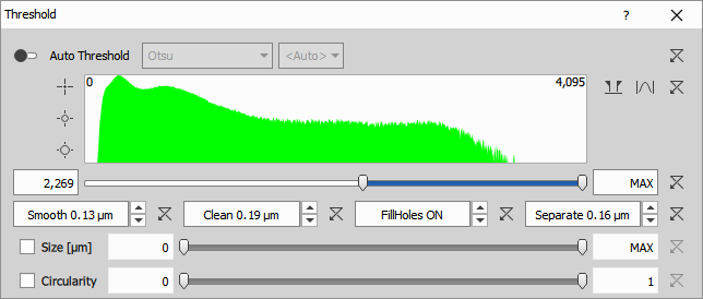
The threshold node performs following steps:
- Selects pixels falling inside the intensity threshold range:
- automatic - the range is determined from the image data frame-by-frame or
- manual - the global range bounds (low, high) is set manually
- Optionally post-processes the binary using morphological operations (in that order):
- Smooth - smooths the object edges (connects nearby objects)
- Clean - removes small objects caused by noise
- Fill Holes - ON / OFF
- Separate - separates objects that are close to each other
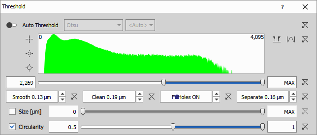
- Optionally filters the objects based on:
- Size - where object EqDiameter must fit into the specified range
- Circularity - where object must fit into the specified range
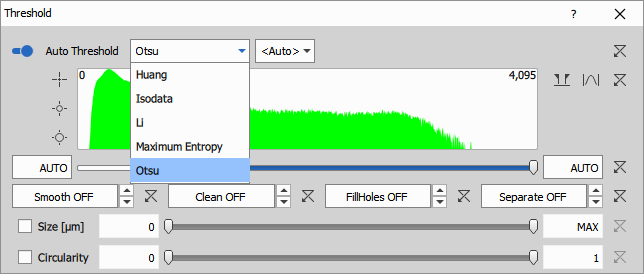

Automatic threshold calculates the intensity range from histogram on each frame independently. Each method sets the threshold differently.
There are these methods available:
Parameters
Input
- A (Channel): Input intensity image to be segmented
Output
- R (Binary): Output segmented binary with the name of the binary layer.
Control
AutoThresholdOn (Number)
AutoThresholdMethod (Text)
AutoThresholdIsDark (Number)
IntensityLow (Number): Minimum intensity value a pixel must have to be part of an object.
IntensityHigh (Number): Maximum intensity value a pixel must have to be part of an object.
Smooth (Number)
Clean (Number)
Fill (Number)
Separate (Number)
FilterBySize (Number)
SizeLow (Number)
SizeHigh (Number)
FilterByCircularity (Number)
CircularityLow (Number)
CircularityHigh (Number)
See also: Threshold (group)
RGB Threshold
Separates objects from the background by turning pixels with RGB values inside given intensity range into objects and everything else into background.
The RGB threshold is very similar to the Threshold. It has more ranges to handle 3 channel image instead of a single channel image.
The ranges can be defined in RGB or HSI color models.
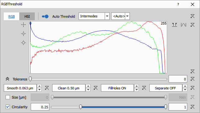
There are three ranges one for each channel: Red, Green Blue and a tolerance to enlarge the range by a given amount.
For a pixel to become an object it must be within all three ranges otherwise it is a background pixel.
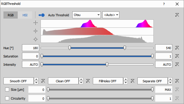
There are three ranges: Hue, Saturation and Intensity. The HSI representation is useful for segmenting objects with a typical hue (stain).
- Hue (2x 0° - 360°) is the color tint (red, yellow, green, and blue). Values in the range and histogram are displayed twice (two full circles 720°) in order to be able to make a range covering 0°/360° from both sides.
- Saturation (0.0-1.0) is colorfulness of the hue. It ranges from gray (0.0) - no hue - to full hue (1.0)
- Intensity (0.0-1.0) is the brightness.
Parameters
Input
- A (Channel): Input intensity image to be segmented
Output
- R (Binary): Output segmented binary with the name of the binary layer.
Control
AutoThresholdOn (Number)
AutoThresholdMethod (Text)
AutoThresholdIsDark (Number)
IsHSI (Number)
RedLow (Number)
RedHigh (Number)
GreenLow (Number)
GreenHigh (Number)
BlueLow (Number)
BlueHigh (Number)
RgbTolerance (Number)
HueLow (Number)
HueHigh (Number)
SaturationLow (Number)
SaturationHigh (Number)
IntensityLow (Number)
IntensityHigh (Number)
Smooth (Number)
Clean (Number)
Fill (Number)
Separate (Number)
FilterBySize (Number)
SizeLow (Number)
SizeHigh (Number)
FilterByCircularity (Number)
CircularityLow (Number)
CircularityHigh (Number)
See also: Threshold (group), Threshold
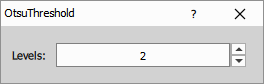
Multilevel Otsu
Perform automatic image thresholding with Otsu method.
Parameters
See also: Threshold (group)
Spot detections
Bright Spots
Finds local extrema using Laplacian of Gaussian filter. The local extrema are then grown to a specified intensity threshold. Resulting objects do not have holes. It is useful for round shapes with similar size like nuclei or spots where the objects are bright and background is dark.
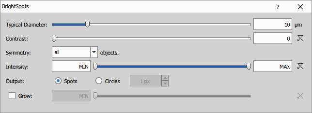
Parameters:
- diameter: typical object diameter in microns
Parameters
Input
- A (Channel): Input intensity image to be segmented
Output
- R (Binary): Output segmented binary with the name of the binary layer.
Control
IsDark (Number)
Diameter (Number)
Contrast (Number)
Symmetry (Number)
IntensityLow (Number)
IntensityHigh (Number)
GrowEnabled (Number)
GrowLimit (Number)
GenerateSpots (Number)
SpotSize (Number)
Dark Spots
Finds local extrema using Laplacian of Gaussian filter. The local extrema are then grown to a specified intensity threshold. It is useful for round shapes with similar size like nuclei or spots where the objects are dark and background is bright.
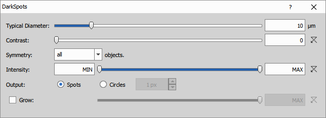
Parameters:
- diameter: typical object diameter in microns
Parameters
Input
- A (Channel): Input intensity image to be segmented
Output
- R (Binary): Output segmented binary with the name of the binary layer.
Control
IsDark (Number)
Diameter (Number)
Contrast (Number)
Symmetry (Number)
IntensityLow (Number)
IntensityHigh (Number)
GrowEnabled (Number)
GrowLimit (Number)
GenerateSpots (Number)
SpotSize (Number)
Special detections
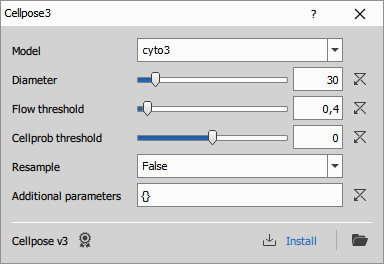
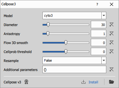
Cellpose3
Uses Python Cellpose v3 to segment cells. For more details see the Cellpose documentation, especially the models and settings.
Parameters
Input
A0 (Channel): Channel to segment.
A1 (Channel, Optional): Channel that is helpful in models trained with images with a nucleus channel.
Output
- R0 (Binary): Segmented binary image.
Control
P0 (Text): Model
P1 (Number): Diameter
P2 (Number): Resample
P3 (Number): Flow threshold
P4 (Number): Cellprob threshold
P5 (Text): Additional parameters
See also: Installing Cellpose, Omnipose for bacterias, Python
Cellpose SAM
Uses Python Cellpose v4 (Segment anything model - SAM) to segment cells.
Connecting the node
[The Cellpose-SAM] has been trained with three different channels for H&E images, and for cellular images it has been trained with the cytoplasm and nuclear channels in any order, with the other channel set to zero.
(see the channels documentation)
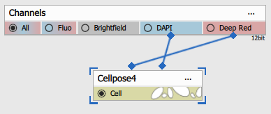
Typical use-case is when single input is connected to a channel with Cell/Cytoplasm expression.
Connecting Nuclei to DAPI improves the segmentation (see the next tab).
| Connected node | Example image |
|---|---|
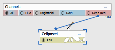 | 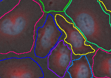 |
Both inputs are connected:
- first to Cell/Cytoplasm channel and
- second to Nuclei channel.
| Connected node | Example image |
|---|---|
 | 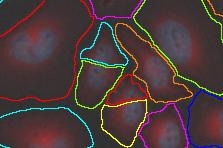 |
First input is connected to RGB (3-channel) H&E stained image. The second channel must remain disconnected.
| Connected node | Example image |
|---|---|
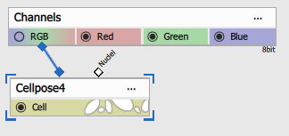 | 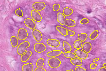 |
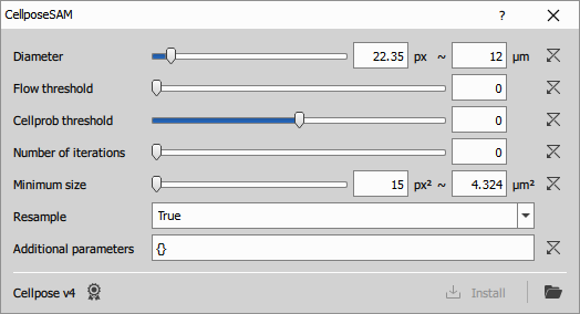
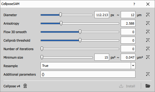
Configuring the node
For explanation of the Cellpose settings see the documentation.
If the NisCellpose4 environment has not been previously installed (typically during NIS-Express installation) the following error is shown:
Installing Cellpose
Until it is installed the settings dialog contains a link to install it.
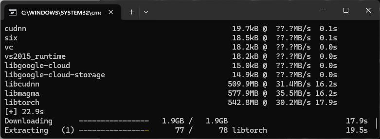
After the environment installation, disable and enable the Python node to update its status.
Parameters
Input
A0 (Channel): Channel to segment.
A1 (Channel, Optional): Channel that is helpful in models trained with images with a nucleus channel.
Output
- R0 (Binary): Segmented binary image.
Control
P0 (Number): Diameter
P1 (Number): Flow threshold
P2 (Number): Cellprob threshold
P3 (Number): Number of iterations
P4 (Number): Minimum size
P5 (Number): Resample
P6 (Text): Additional parameters
See also: Omnipose for bacterias, Python
EfficientV2-UNet
Runs a Python EfficientV2-UNet model to segment histological RGB images. For details and training code, see the EfficientV2-UNet repository on GitHub.
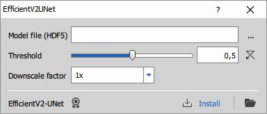
- Model file: Path to a trained model saved as an HDF5 (.h5) file
- Threshold: Threshold applied to the model’s output probability map to produce the final binary mask
- Downscale: Downscales the input image before prediction to speed up processing and reduce memory usage.
Parameters
Input
- A0 (Channel)
Output
- R0 (Binary)
Control
mode (Number)
code (Text)
refresh (Number)
environmentDesc (Text)
outprocType (Number)
environmentName (Text)
outprocPath (Text)
editingOutsidePath (Text)
editingOutsideEnabled (Number)
pyParDefs (Text)
devModeKey (Text)
description (Text)
P0 (Text)
P1 (Number)
P2 (Number)
Homogeneous Area
Detect object on a homogenous background based on their edges
Parameters
IHC Classification
Diagnose Immunohistochemistry automatically
Parameters
InstanSeg
Runs a Python InstanSeg model to segment brightfield or fluorescence images. For details and training code, see the InstanSeg repository on GitHub.
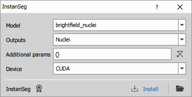
By default, the node provides two built-in models: brightfield_nuclei and fluorescence_nuclei_and_cells.
To use a custom model, click the folder button (after installation). It will open the environment folder ...\PythonEnvs\NisInstanSeg. From there, navigate to ...\PythonEnvs\NisInstanSeg\lib\site-packages\instanseg\bioimageio_models where the models are stored, and update model-index.json to include your model. Finally, enter your model’s name in the node GUI model selection. Note that custom models are currently not supported by the NIS-Elements GA3 executor.
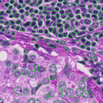
Segmentation using InstanSeg’s built-in model “brightfield_nuclei” on an H&E image.
H&E image: InstanSeg (v0.1.1)
- Model: Model name; choose from the list or enter your custom model name
- Outputs: Some models produce both nuclei and cell masks. Choose which output to generate. If All is selected, the node always has two outputs; when the selected model does not support two outputs, the second output will be empty.
- Additional params: Additional options as a JSON dictionary, passed directly to
InstanSeg.eval_small_image - Device: Select where segmentation runs: CPU or GPU (NVIDIA/CUDA).
Parameters
Input
- A0 (Channel)
Output
- R0 (Binary)
Control
mode (Number)
code (Text)
refresh (Number)
environmentDesc (Text)
outprocType (Number)
environmentName (Text)
outprocPath (Text)
editingOutsidePath (Text)
editingOutsideEnabled (Number)
pyParDefs (Text)
devModeKey (Text)
description (Text)
P0 (Text)
P1 (Text)
P2 (Text)
P3 (Text)
Labels to Binary
Converts a labeled image into a binary layer.
Parameters
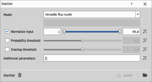
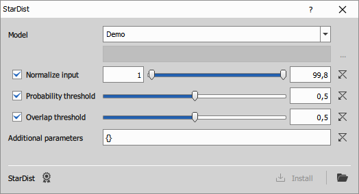
StarDist
Runs a Python StarDist model to segment images. For details and training code, see the StarDist repository on GitHub.
When installation fails
OSError: [WinError 1314] A required privilege is not held ...If this error happens the user has no right to create symbolic links.
Th easiest solution on Windows 11 is to Enable Windows Developer Mode: Settings → System → For Developers → Developer Mode
By default, the node provides these built-in models for 2D:
- Versatile fluo nuclei:
2D_versatile_fluo - Versatile H&E nuclei:
2D_versatile_he - DSB 2018:
2D_paper_dsb2018 - Demo:
2D_demo
and this for 3D:
- Demo:
3D_demo
To use a custom model, select Custom model in selection and click the ... button. Than select folder containing your model.
- Model: Select built-in or custom model
- Normalize input: If enabled, the input image will be normalized to floating-point format so that the selected intensity percentiles are mapped to the 0–1 range.
- Probability threshold: If enabled, overrides the model’s default probability threshold with the specified value.
- Overlap threshold: If enabled, overrides the model’s default overlap (NMS) threshold with the specified value.
- Additional parameters: Additional options as a JSON dictionary, passed directly to
StarDist2D.predict_instances
Parameters
Input
- A0 (Channel)
Output
- R0 (Binary)
Control
mode (Number)
code (Text)
refresh (Number)
environmentDesc (Text)
outprocType (Number)
environmentName (Text)
outprocPath (Text)
editingOutsidePath (Text)
editingOutsideEnabled (Number)
pyParDefs (Text)
devModeKey (Text)
description (Text)
P0 (Text)
P1 (Text)
P2 (Number)
P3 (Number)
P4 (Number)
P5 (Number)
P6 (Number)
P7 (Number)
P8 (Number)
P9 (Text)
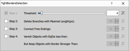
Tight Borders
Performs the segmentation of binary result using the tight borders detection.
- Threshold detects pixels with intensities higher than the specified threshold value. The higher the value the less objects are detected.
- Delete Branches with Maximal Length (px): Deletes branches with length smaller than the length specified.
- Connect Free Endings: Connects free endings of the neighboring branches.
- Vanish Objects with EqDia less than: Objects with EqDia (equivalent diameter of a circular object) smaller than the defined value will be deleted.
- But Keep Objects with Border Stronger Than: Objects with their border stronger than the defined value will be kept.
Parameters
Interactive
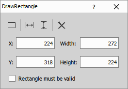
Draw Rectangle
Draws a rectangle (region of interest) that is applied to all frames and creates a separate binary layer.
You can set the rectangle position and size manually in the edit boxes, or click Draw rectangle to draw it directly in the image.
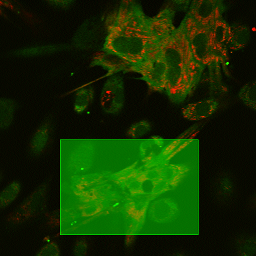
- X, Y, Width, Height: Define the rectangle.
- Rectangle must be valid: Throws an error during execution if the rectangle is missing or invalid. Useful in wizards when the user must define the ROI.
Parameters
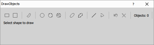
Draw Objects
Draws objects that are applied to all frames and creates a separate binary layer.
Select the desired shape by clicking a button, then draw it directly in the image. You can undo the last shape or remove all objects.
Overlapping objects are merged into a single object. You can choose whether the output is a binary mask or a labeled mask by toggling the Color by ID button.
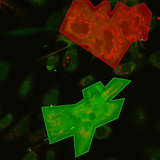
Supported shapes:
- rectangle
- square
- polygon
- circle
- ellipse
- line
- polyline
After clicking a shape button, drawing instructions are displayed.